Electronics
| Authors: | Hernando Barragán; Casey Reas; Abhik Pal (p5 port) |
|---|---|
| Copyright: | This tutorial is “Extension 5” from Processing: A Programming Handbook for Visual Designers and Artists, Second Edition, published by MIT Press. © 2014 MIT Press. If you see any errors or have comments, please let us know. The tutorial was ported to p5 by Abhik Pal. If you see any errors or have comments, open an issue on either the p5 or Processing repositories. |
Software is not limited to running on desktop computers, laptops, tablets, and phones. Contemporary cameras, copiers, elevators, toys, washing machines, and artworks found in galleries and museums are controlled with software. Programs written to control these objects use the same concepts discussed earlier in this book (variables, control structures, arrays, etc.), but building the physical parts requires learning about electronics. This text introduces the potential of electronics with examples from art and design and discusses basic terminology and components. Examples written with Wiring and Arduino (two electronics toolkits related to Processing) are presented and explained.
Electronics in the arts
Electronics emerged as a popular material for artists during the 1960s. Artists such as Naum Gabo and Marcel Duchamp used electrical motors in prior decades, but the wide interest in kinetic sculpture and the foundation of organizations such as Experiments in Art and Technology (E.A.T.) are evidence of a significant new emphasis. For instance, in The Machine exhibition at The Museum of Modern Art in 1968, Wen-Ying Tsai exhibited Cybernetic Sculpture, a structure made of vibrating steel rods illuminated by strobe lights flashing at high frequencies. Variations in the vibration frequency and the light flashes produced changes in the perception of the sculpture. The sculpture responded to sound in the surrounding environment by changing the frequency of the strobe lights. Peter Vogel, another kinetic sculpture pioneer, created sculptures that generate sound. The sculptures have light sensors (photocells) that detect and respond to a person’s shadow when she approaches the sculpture. The sculptures are built almost entirely with electrical components. The organization of these components forms both the shape of the sculpture and its behavior. Other pioneers during the 1960s include Nam June Paik, Nicolas Schöffer, James Seawright, and Takis.
The range of electronic sculpture created by contemporary artists is impressive. Tim Hawkinson produces sprawling kinetic installations made of cardboard, plastic, tape, and electrical components. His Überorgan (2000) uses mechanical principles inspired by a player piano to control the flow of air through balloons the size of whales. The air is pushed through vibrating reeds to create tonal rumbles and squawks. This physical energy contrasts with the psychological tension conveyed through Ken Feingold’s sculptures. His If/Then (2001) is two identical, bald heads protruding from a cardboard box filled with packing material. These electromechanical talking heads debate their existence and whether they are the same person. Each head listens to the other and forms a response from what it understands. Speech synthesis and recognition software are used in tandem with mechanisms to animate the faces – the result is uncanny.
The works of Maywa Denki and Crispin Jones are prototypical of a fascinating area of work between art and product design. Maywa Denki is a Japanese art unit that develops series of products (artworks) that are shown in product demonstrations (live performances). Over the years, they have developed a progeny of creatures, instruments, fashion devices, robots, toys, and tools – all animated by motors and electricity. Devices from the Edelweiss Series include Marmica, a self-playing marimba that opens like a flower, and Mustang, a gasoline-burning aroma machine for people who love exhaust fumes. Crispin Jones creates fully functioning prototypes for objects that are critical reflections of consumer technologies. Social Mobiles (SoMo), developed in collaboration with IDEO, is a set of mobile phones that address the frustration and anger caused by mobile phones in public places. The project humorously explores ways mobile phone calls in public places could be made less disruptive. The SoMo 1 phone delivers a variable electrical shock to the caller depending on how loud the person at the other end of the conversation is speaking. The ringtone for SoMo 4 is created by the caller knocking on their phone. As with a knock on a door, the attitude or identity of the caller is revealed through the sound. Related artists include the Bureau of Inverse Technology, Ryota Kuwakubo, and the team of Tony Dunne and Fiona Raby.
As electronic devices proliferate, it becomes increasingly important for designers to consider new ways to interact with these machines. Working with electronics is an essential component of the emerging interaction design community. The Tangible Media Group (TMG) at the MIT Media Laboratory, led by Hiroshi Ishii, pioneered research into tangible user interfaces to take advantage of human senses and dexterity beyond screen GUIs and clicking a mouse. Curlybot is a toy that can record and play back physical movement. It remembers how it was moved and can replay the motion including pauses, changes in speed, and direction. MusicBottles are physical glass bottles that trigger sounds when they are opened. To the person who opens the bottles, the sounds appear to be stored within the bottles, but technically, custom-designed electromagnetic tags allow a special table to know when a bottle has been opened, and the sound is played through nearby speakers. These and other projects from the TMG were instrumental in moving research in interface design away from the screen and into physical space. Research labs at companies like Sony and Philips are other centers for research and innovation into physical interaction design. Academic programs such as New York University’s Interactive Telecommunication Program, the Design Interactions course at the Royal College of Art, and the former Interaction Design Institute Ivrea have pioneered educational strategies within in this area.
Electricity
Electricity is something we use daily, but it is difficult to understand. Its effect is experienced in many ways, from observing a light turn on to noticing the battery charge deplete on a laptop computer.
Electrical current is a stream of moving electrons. They flow from one point to another through a conductor. Some materials are better conductors than others. Sticking a fork in a light socket is dangerous because metal is a good conductor and so is your body. The best conductors are copper, silver, and gold. A resistor is the opposite of a conductor. Resistance is the capability of a material to resist the flow of electrons. A substance with a very high resistance is an insulator. Plastic and rubber are excellent insulators, and for this reason they are used as the protective covering around wires. Electrical energy, the difference of electrical potential between two points, is called voltage. The amount of electrical charge per second that flows through a point is the current. Resistance is measured in units called ohms, voltage is measured in volts, and current is measured in amperes (amps). The relation between the three is easiest to understand through an analogy of water flowing through a hose. As explained by the educators Dan O’Sullivan and Tom Igoe:
The flow of water through a hose is like the flow of electricity through a circuit. Turning the faucet increases the amount of water coming through the hose, or increases the current (amps). The diameter of the hose offers resistance to the current, determining how much water can flow. The speed of the water is equivalent to voltage. When you put your thumb over the end of the hose, you reduce the diameter of the pathway of the water. In other words, the resistance goes up. The current (that is, how much water is flowing) doesn’t change, however, so the speed of the water, or voltage, has to go up so that all the water can escape… [1]
Electrical current flows in two ways: direct current (DC) and alternating current (AC). A DC signal always flows in the same direction and an AC signal reverses the direction of flow at regular intervals. Batteries and solar cells produce DC signals, and the power that comes from wall sockets is an AC signal:
.svg)
Depending on your country, the AC power source coming into your home is between 100 and 240 volts. Most home appliances can directly use AC current to operate, but some use a power supply to convert the higher-potential AC current into DC current at smaller voltages. A common example of this type of power supply are the black plastic boxes (a k a power bricks, power adapters, wall warts) that are used to power laptops or mobile phones from the home AC power source. Most desktop computers have an internal power supply to convert the AC source to the 12-volt and 5-volt DC supply necessary to run the internal electronics. Low voltages are generally safer than high voltages, but it’s the amount of current (amps) that makes electricity dangerous.
Components
Electronic components are used to affect the flow of electricity and to convert electrical energy into other forms such as light, heat, and mechanical energy. There are many different components, each with a specific use, but here we introduce four of the most basic types: resistor, capacitor, diode, and transistor.
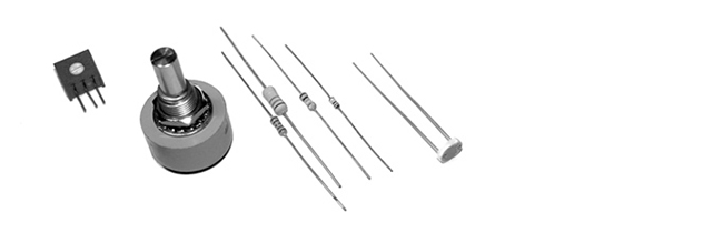
Resistor
A resistor limits (provides resistance to) the flow of electricity. Resistors are measured in units called ohms. The value 10 ohms is less resistance than 10,000 (10K) ohms. The value of each resistor is marked on the component with a series of colored bands. A variable resistor that changes its resistance when a slider, knob, or dial attached to it is turned is called a potentiometer or trimmer. Variable resistors are designed to change in response to different environmental phenomena. For example, one that changes in response to light is called a photoresistor or photocell, and one that changes in response to heat is called a thermistor. Resistors can be used to limit current, reduce voltage, and perform many other essential tasks.
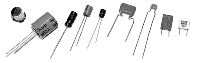
Capacitor
A capacitor stores electrons i.e. electrical charge; it gains charge when current flows in, and it releases charge (discharges) when the current flows out. This can smooth out the dips and spikes in a current signal. Capacitors are combined with resistors to create filters, integrators, differentiators, and oscillators. A simple capacitor is two parallel sheets of conductive materials, separated by an insulator. Capacitors are measured in units called farads. A farad is a large measurement, so most capacitors you will use will be measured in microfarads (µF), picofarads (pF), or nanofarads (nF).
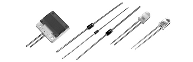
Diode
Current flows only in one direction through a diode. One side is called the cathode (marked on the device with a line) and the other is the anode. Current flows when the anode is more positive than the cathode. Diodes are commonly used to block or invert the negative part of an AC signal. A light-emitting diode (LED) is used to produce light. The longer wire coming out of the LED is the anode and the other is the cathode. LEDs come in many sizes, forms, colors, and brightness levels.
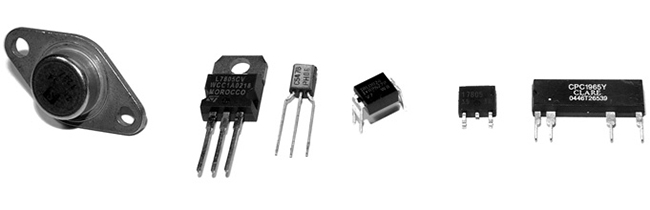
Transistor
A transistor can be used as an electrical switch or an amplifier. A bipolar transistor has three leads (wires) called the base, collector, and emitter. Depending on the type of transistor, applying current to the base either allows current to flow or stops it from flowing through the device from the collector to the emitter. Transistors make it possible for the low current from a microcontroller to control the much higher currents necessary for motors and other power-hungry devices, and thus to turn them on and off.
Circuits
An electrical circuit is a configuration of components, typically designed to produce a desired behavior such as decreasing the current, filtering a signal, or turning on an LED. The following simple circuit can be used to turn a light on and off:

This simple electric circuit is a closed loop with an energy source (battery), a load (lightbulb) that offers a resistance to the flow of electrons and transforms the electric energy into another form of energy (light), wires that carry the electricity, and a switch to connect and disconnect the wires. The electrons move from one end of the battery, through the load, and to the other end.
Circuits are usually represented with diagrams. A circuit diagram uses standardized symbols to represent specific electrical components. It is easier to read the connections on a diagram than on photographs of the components. A diagram of the simple circuit above could look like this:

Circuits are often prototyped on a “breadboard,” a rectangular piece of plastic with holes for inserting wires. A breadboard makes it easy to quickly make variations on a circuit without soldering (fusing components together with a soft metal). Conductive strips underneath the surface connect the long horizontal rows at the top and bottom of the board and the short vertical rows within the middle:

Circuits are tested with a multimeter, an instrument to measure volts, current, resistance, and other electrical properties. A multimeter allows the electrical properties of the circuit to be read as numbers and is necessary for debugging. Analog multimeters have a small needle that moves from left to right, and digital multimeters have a screen that displays numbers. Most multimeters have two metal prongs to probe the circuit and a central dial to select between different modes.
Commonly used circuits are often condensed into small packages. These integrated circuits (ICs, or chips) contain dense arrangements of miniaturized components. They are typically small, black plastic rectangles with little metal pins sticking out of the sides. Like objects in software, these devices are used as building blocks for creating more complicated projects. ICs are produced to generate signals, amplify signals, control motors, and perform hundreds of other functions. They fit neatly into a breadboard by straddling the gap in the middle.
Microcontrollers and I/O boards
Microcontrollers are small and simple computers. They are the tiny computer brains that automate many aspects of contemporary life, through their activities inside devices ranging from alarm clocks to airplanes. A microcontroller has a processor, memory, and input/output interfaces enclosed within a single programmable unit. They range in size from about 1 × 1 cm to 5 × 2 cm. Like desktop computers, they come in many different configurations. Some have the same speed and memory as a personal computer from twenty years ago, but they are much less powerful than current machines, as this comparison tables shows:
| Model | Speed | Memory | Cost |
|---|---|---|---|
| Apple Macintosh (1984) | 8MHz | 128 Kb | $2500 |
| Atmel ATmega128-8AC Microcontroller | 8MHz | 128 Kb | $15 |
| Apple Mac Mini (2006) | 1500 MHz | 512,000 Kb | $600 |
Small metal pins poking out from a microcontroller’s edges allow access to the circuits inside. Each pin has its own role. Some are used to supply power, some are for communication, some are inputs, and others can be set to either input or output. The relative voltage at each input pin can be read through software, and the voltage can be set at each output pin. Some pins are reserved for communication. They allow a microcontroller to communicate with computers and other microcontrollers through established communication protocols such as RS-232 serial.
Microcontrollers can be used to build projects directly, but they are often packaged with other components onto a printed circuit board (PCB) to make them easier to use for beginners and for rapid prototyping. We call these boards I/O boards (input/output boards) because they are used to get data in and out of a microcontroller. They are also called microcontroller modules. We’ve created three informal groups – bare microcontrollers, programmable I/O boards, and tethered I/O boards – to discuss different ways to utilize microcontrollers in a project.
Bare microcontrollers
Working directly with a bare microcontroller is the most flexible but most difficult way to work. It also has the potential to be the least expensive way of building with electronics, but this economy can be offset by initial development costs and the extra time spent learning how to use it. Microchip PIC and Atmel AVR are two popular families of microcontrollers. Each has variations ranging from simple to elaborate that are appropriate for different types of projects. The memory, speed, and other features effect the cost, the number of pins, and the size of the package. Both families feature chips with between eight and 100 pins with prices ranging from under $1 to $20. PIC microcontrollers have been on the market for a longer time, and more example code, projects, and books are available for beginners. The AVR chips have a more modern architecture and a wider range of open-source programming tools. Microcontrollers are usually programmed in the C language or their assembly language, but it’s also possible to program them in other languages such as BASIC. If you are new to electronics and programming, we don’t recommend starting by working directly with PIC or AVR chips. In our experience, beginners have had more success with the options introduced below.
Programmable I/O boards
A programmable I/O board is a microcontroller situated on a PCB with other components to make it easier to program, attach/detach components, and turn on and off. These boards typically have components to regulate power to protect the microcontroller and a USB or RS-232 serial port connector to make it easy to attach cables for communication. The small pins on the microcontroller are wired to larger pins called headers, which make it easy to insert and remove sensors and motors. Small wires embedded within the PCB connect pins to a corresponding header. Small reset switches make it easy to restart the power without having to physically detach the power supply or battery.
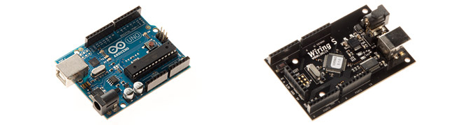
Within the context of this book, the most relevant I/O boards are Wiring and Arduino. Both were created as tools for designers and artists to build prototypes and to learn about electronics. Both boards use the Wiring language to program their microcontrollers and use a development environment built from the Processing environment. In comparison to the Processing language, the Wiring language provides a similar level of control and ease of use within its domain. They share common language elements when possible, but Wiring has some functions specific to programming microcontrollers and omits the graphics programming functions within Processing. Like Processing programs, Wiring programs are translated into another language before they are run. When a program written with the Wiring language is compiled, it’s first translated into the C/C++ language and then compiled using a C/C++ compiler.
Tethered I/O boards
A tethered I/O board is used to get sensor data into a computer and to control physical devices (motors, lights, etc.) without the need to program the board. A computer already has many input and output devices such as a monitor, mouse, and keyboard; and tethered I/O boards provide a way to communicate between more exotic input devices such as light sensors and video cameras, and output devices such as servomotors and lights. These boards are designed to be easy to use. They often do not require knowledge of electronics because sensors and motors can be plugged directly into the board and do not need to interface with other components. Messages are sent and received from the boards through software such as Processing, Max, Flash, and many programming languages. This ease of use often comes at a high price.
Sensors
Physical phenomena are measured by electronic devices called sensors. Different sensors have been invented to acquire data related to touch, force, proximity, light, orientation, sound, temperature, and much more. Sensors can be classified into groups according to the type of signals they produce (analog or digital) and the type of phenomena they measure. Analog signals are continuous, but digital signals are constrained to a range of values (e.g., 0 to 255):

Most basic analog sensors utilize resistance. Changes in a physical phenomenon modify the resistance of the sensor, therefore varying the voltage output through the sensor. An analog-to-digital converter can continuously measure this changing voltage and convert it to a number that can be used by software. Sensors that produce digital signals send data as binary values to an attached device or computer. These sensors use a voltage (typically between 3.5 and 5 volts) as ON (binary digit 1 or TRUE) and no voltage as a OFF (binary digit 0 or FALSE). More complex sensors include their own microcontrollers to convert the data to digital signals and to use established communication protocols for transmitting these signals to another computer.
Touch and Force
Sensing of touch and force is achieved with switches, capacitive sensors, bend sensors, and force-sensitive resistors. A switch is the simplest way to detect touch. A switch is a mechanism that stops or allows the flow of electricity depending on its state, either open (OFF) or closed (ON). Some switches have many possible positions, but most can only be ON or OFF. Touch can also be detected with capacitive sensors. These sensors can be adjusted to detect the touch and proximity (within a few millimeters) of a finger to an object. The sensor can be positioned underneath a nonconductive surface like glass, cardboard, or fabric. This type of sensor is often used for the buttons in an elevator. A bend (flex) sensor is a thin strip of plastic that changes its resistance as it is bent. A force-sensitive resistor (FSR or force sensor) changes its resistance depending on the magnitude of force applied to its surface. FSRs are designed for small amounts of force like the pressure from a finger, and they are available in different shapes including long strips and circular pads.
Presence and distance
There are a wide variety of sensors to measure distance and determine whether a person is present. The simplest way to determine presence is a switch. A switch attached to a door, for example, can be used to determine whether it is open or closed. A change in the state (open or closed) means someone or something is there. Switches come in many different shapes and sizes, but the category of small ones called microswitches are most useful for this purpose. The infrared (IR) motion detectors used in security systems are another simple way to see if something is moving in the environment. They can’t measure distance or the degree of motion, but they have a wide range, and some types can be purchased at hardware stores. IR distance sensors are used to calculate the distance between the sensor and an object. The distance is converted into a voltage between 0 and 5 volts that can be read by a microcontroller. Ultrasonic sensors are used for measuring up to 10 meters. This type of device sends a sound pulse and calculates how much time it takes to receive the echo.
Light
Sensors for detecting light include photoresistors, phototransistors, and photodiodes. A photoresistor (also called a photocell) is a component that changes its resistance with varying levels of light. It is among the easiest sensors to use. A phototransitor is more sensitive to changes in light and is also easy to use. Photodiodes are also very sensitive and can respond faster to changing light levels, but they are more complex to interface with a microcontroller. Photodiodes are used in the remote control receivers of televisions and stereos.
Position and orientation
A potentiometer is a variable resistor that works by twisting a rotary knob or by moving a slider up and down. The potentiometer’s resistance changes with the rotation or up/down movement, and this can affect the voltage level within a circuit. Most rotary potentiometers have a limited range of rotation, but some are able to turn continuously. A tilt sensor is used to crudely measure orientation (up or down). It is a switch with two or more wires and a small metal ball or mercury in a box that touches wires in order to complete a circuit when it is in a certain orientation. An accelerometer measures the change in movement (acceleration) of an object that it is mounted to. Tiny structures inside the device bend as a result of momentum, and the amount of bending is measured. Accelerometers are used in cameras to control image stabilization and in automobiles to detect rapid deceleration and release airbags. A digital compass calculates orientation in relation to the earth’s magnetic field. The less expensive sensors of this type have a lower accuracy, and they may not work well when situated near objects that emit electromagnetic fields (e.g., motors).
Sound
A microphone is the simplest and most common device used to detect and measure sound. Sudden changes in volume are the easiest sound elements to read, but processing the sound wave with software (or special hardware) makes it possible to detect specific frequencies or rhythms. A microphone usually requires extra components to amplify the signal before it can be read by a microcontroller. Piezo electric film sensors, commonly used in speakers and microphones, can also be used to detect sound. Sampling a sound wave with a microcontroller can dramatically reduce the quality of the audio signal. For some applications, it’s better to sample and analyze sound through a desktop computer and to communicate the desired analysis information to an attached microcontroller.
Temperature
A thermistor is a device that changes its resistance with temperature. These sensors are easy to interface, but they respond slowly to changes. To quantitatively measure temperature, a more sophisticated device is needed. Flame sensors are tuned to detect open flames such as lighters and candles.
Sensors and communication
Analog voltage signals from sensors can’t be directly interpreted by a computer, so they must be converted to a digital value. Some microcontrollers provide analog-to-digital converters (ADC or A/D) that measure variations in voltage at an input pin and convert it to a digital value. The range of values depends on the resolution of the ADC; common resolutions are 8 and 10 bits. At 8-bit resolution, an ADC can represent \(2^8\) (256) different values, where 0 volts corresponds to the value 0 and 5 volts corresponds to 255. A 10-bit ADC provides 1024 different values, where 5 volts corresponds to the value 1023.
Data is sent and received between microcontrollers and computers according to established data protocols such as RS-232 serial, USB, MIDI, TPC/IP, Bluetooth, and other proprietary formats like I2C or SPI. Most electronics prototyping kits and microcontrollers include an RS-232 serial port, and this is therefore a convenient way to communicate. This standard has been around for a long time (it was developed in the late 1960s) and it defines signal levels, timing, physical plugs, and information exchange protocols. The physical RS-232 serial port has largely been replaced in computers by the faster and more flexible (but more complex) universal serial bus (USB), but the protocol is still widely used when combining the USB port with software emulation.
Because a device can have several serial ports, a user must specify
which serial port to use for data transmission. On most Windows
computers, serial port names are COMx, where x can be 1, 2, 3,
etc. On UNIX-based systems (Mac OS X and Linux), serial devices are
accessed through files in the /dev/ directory. After the serial
port is selected, the user must specify the settings for the port.
Communication speed will vary with devices, but typical values are
9600, 19,200, and 115,200 bits per second. Once the ports are open for
communication on both devices, it is possible to send and receive
data.
The following examples connect sensors and actuators to a Wiring or Arduino board and communicate the data between the I/O board and a Processing application. When the Wiring and Arduino boards are plugged into a computer’s USB port, it appears on the computer as a serial port, making it possible to send/receive data on it. The Wiring board has two serial ports called Serial and Serial1; the Arduino board has one called Serial. Serial is directly available on the USB connector located on the board surface. Serial1 is available through the Wiring board digital pin numbers 2(Rx) and 3(Tx) for the user’s applications.
Example 1: Switch (Code below)
This example sends the status of a switch (ON or OFF) connected to the Wiring or Arduino board to a Processing application running on a computer. Software runs on the board to read the status of a switch connected on digital pin 4. This value 1 is sent to the serial port continuously while the switch is pressed and 0 is sent continuously when the switch is not pressed. The Processing application continuously receives data from the board and assigns the color of a rectangle on the screen depending on the value of the data. When the switch is pressed the rectangle’s color changes from black to light gray.
Example 2: Light sensor (Code below)
This example brings data from a light sensor (photoresistor) connected to the Wiring or Arduino board’s analog input pin 0 into a Processing application running on a computer. Software runs on the board to send the value received from the light sensor to the serial port. Because the light sensor is plugged into an analog input pin, the analog voltage coming into the board is converted into a digital number before it is sent over the serial port. The Processing application changes the color of a rectangle on-screen according to the value sent from the board. The rectangle exhibits grays from black to white according to the amount of light received by the sensor. Cover and uncover the sensor with your hand to see a large change.
Controlling physical media
Actuators are devices that act on the physical world. Different types of actuators can create light, motion, heat, and magnetic fields. The digital output pin on a microcontroller can be set to a voltage of 0 or 5 volts. This value can be used to turn a light or motor on or off, but finer control over brightness and speed requires an analog output. By using a digital to analog converter (DAC), a discretized signal can be directly generated as illustrated in the previous figure. If desired, some smoothing can be added to obtain the desired analog signal. When a DAC is not available or not justified in terms of cost or conversion speed, another approach is to use a technique called pulse-width modulation (PWM). This is turning a digital output ON and OFF very quickly to simulate values between 0 and 5 volts. If the output is 0 volts for 90% of the time and 5 volts for 10%, this is called a 10% duty cycle. Following smoothing, it emulates an analog voltage of 0.5 volts. An 80% duty cycle with smoothing emulates a 4-volt signal:

The PWM technique can be used to dim a light, run a motor at a slow speed, and control the frequency of a tone through a speaker. In some applications, any necessary smoothing is obtained for free e.g. the inertia in a motor can average out the PWM duty cycle and result in smooth motion.
Light
Sending current through a light-emitting diode (LED) is the simplest way to get a microcontroller to control light. An LED is a semiconductor device that emits monochromatic light when a current is applied to it. The color (ranging from ultraviolet to infrared) depends on the semiconductor material used in its construction. LEDs have a wide range of applications from simple blinking indicators and displays to street lamps. They have a long life and are very efficient. Some types of LEDs and high-power LEDs require special power arrangements and interfacing circuits before they can be used with microcontrollers. Incandescent, fluorescent, and electroluminescent light sources always require special interfacing circuits before they can be controlled.
Motion
Motors are used to create rotational and linear movement. The rated voltage, the current drawn by the motor, internal resistance, speed, and torque (force) are factors that determine the power and efficiency of the motor. Direct current (DC) motors turn continuously at very high speeds and can switch between a clockwise and counterclockwise direction. They are usually interfaced with a gearbox to reduce the speed and increase the power. Servomotors are modified DC motors that can be set to any position within a 180-degree range. These motors have an internal feedback system to ensure they remain at their position. Stepper motors move in discrete steps in both directions. The size of the steps depends on the resolution of the motor. Solenoids move linearly (forward or back instead of in circles). A solenoid is a coil of wire with a shaft in the center. When current is applied to the coil, it creates a magnetic field that pulls or pushes the shaft, depending on the type. Muscle wire (shape memory alloy or nitinol) is a nickel-titanium alloy that contracts when power is applied. It is difficult to work with and is slower than motors, but requires less current and is smaller. DC and stepper motors need special interfacing circuits because they require more current than a microcontroller can supply through its output pins. H-bridge chips simplify this interface.
Switches
Relays and transistors are used to turn on and off electric current. A relay is an electromechanical switch. It has a coil of wire that generates a magnetic field when an electrical current is passed through. The magnetic field pulls together the two metal contacts of the relay’s switch. Solid-state relays without moving parts are faster than electromechanical relays. Using relays makes it possible to turn ON and OFF devices that can’t be connected directly to a microcontroller. These devices include home appliances, 120-volt light bulbs, and all other devices that require more power than the microcontroller can provide. Transistors can also behave like switches. Because they operate electronically and not mechanically, they are much faster than relays.
Sound
Running a signal from a digital out or PWM pin to a small speaker is the easiest way to produce a crude, buzzing noise. For more sophisticated sounds, attach these pins to tone-generator circuits created with a 555 timer IC, capacitors, and resistors. Some chips are designed specifically to record and play back sound. Others are sound synthesizers that can synthesize speech by configuring stored phonemes.
Temperature
Temperature can be controlled by a Peltier junction, a device that works as a heat pump. It transforms electricity into heat and cold at the same time by extracting thermal energy from one side (cooling) into the other side (heating). It can also work in reverse, applying heat or cold to the proper surface to produce an electrical current. Because this device consumes more current than a microcontroller can handle in an output pin, it must be interfaced using transistors, relays, or digital switches like the ones described above.
The following examples demonstrate how to control lights and motors attached to an I/O board through a Processing program:
Example 3: Turn a light on and off (Code below)
This example sends data from a Processing program running on a computer to a Wiring or Arduino board to turn a light ON or OFF. The program continually writes an H to the serial port if the cursor is inside the rectangle and writes a L if it’s not. Software running on the board receives the data and checks for the value. If the value is H, it turns on a light connected to the digital I/O pin number 4, and if the value is L, it turns off the light. The light always reflects the status of the rectangle on the computer’s screen.
Example 4: Control a servomotor (Code below)
This example controls the position of a servomotor through an interface within a Processing program. When the mouse is dragged through the interface, it writes the position data to the serial port. Software running on a Wiring or Arduino board receives data from the serial port and sets the position of a servomotor connected to the digital I/O pin number 4.
Example 5: Turn a DC motor on and off (Code below)
This example controls a DC motor from a Processing program. The program displays an interface that responds to a mouse click. When the mouse is clicked within the interface, the program writes data to the serial port. Software running on the board receives data from the serial port and turns the DC motor connected to the PWM pin ON and OFF. The DC motor is connected to the board through an L293D chip to protect the microcontroller from current spikes caused when the motor turns on.
Conclusion
Electronic components and microcontrollers are becoming more common in designed objects and interactive artworks. Although the programming and electronics skills required for many projects call for an advanced understanding of circuits, a number of widely used and highly effective techniques can be implemented and quickly prototyped by novices. The goal of this text is to introduce electronics and to provide enough information to encourage future exploration. As you pursue electronics further, we recommend that you read CODE by Charles Petzold to gain a basic understanding of how electronics and computers work, and we recommend that you read Physical Computing by Dan O’Sullivan and Tom Igoe for a pragmatic introduction to working with electronics. Practical Electronics for Inventors by Paul Scherz is an indispensable resource, and the Engineer’s Mini Notebook series by Forrest M. Mims III is an excellent source for circuit designs. The Web is a deep resource for learning about electronics, and there are many excellent pages listed below in Resources. The best way to learn is by making projects. Build many simple projects and work through the examples in Physical Computing to gain familiarity with the different components.
Code
To run these examples, unlike the other examples in this book, you will need additional equipment. They require either a Wiring (wiring.org.co) or Arduino (www.arduino.cc) board and the following:
- USB cable (used to send data between board and computer)
- 9–15V 1000mA power supply or 9V battery
- 22-gauge solid core wire (get different colors)
- Breadboard
- Switch
- Resistors (10K ohm for the switch circuits, 330 ohm for the LEDs, 1K ohm for the photoresistor)
- LEDs
- Servo motor (Futaba or Hi-Tech)
- DC motor (a generic DC motor like the ones in toy cars)
- L293D or SN754410 H-Bridge Integrated Circuit
- Wire cutters
- Wire strippers
- Needlenose pliers
This equipment can be purchased from an electronics store such as Radio Shack or from an online vendor.
Each example presents two programs: code for the I/O board and code for Processing. Diagrams and breadboard illustrations for the examples are presented side by side in this tutorial to reinforce the connections between the two representations. Learning to translate a circuit diagram into a physical circuit is one of the most difficult challenges when starting to work with electronics.
The Wiring or Arduino software environment is necessary to program each board. These environments are built on top of the Processing environment, but they have special features for uploading code to the board and monitoring serial communication. Both can be downloaded at no cost from their respective websites and both are available for Linux, Macintosh, and Windows.
The pySerial library is also required to communicate with the Arduino/Wiring boards with p5. Refer to the installation instructions on the pySerial documentation
The examples that follow assume the I/O board is connected to your computer and serial communication is working. Before working with these examples, get one of the simple pySerial library examples to work. For the most up-to-date information and troubleshooting tips, refer to the pySerial documentation. The Wiring and Arduino websites have additional information.

Example 1A: Switch (Wiring/Arduino)
// Code for sensing a switch status and writing the value to the serial port

int switchPin = 4;  // Switch connected to pin 4

void setup() {
  pinMode(switchPin, INPUT);  // Set pin 0 as an input
  Serial.begin(9600);         // Start serial communication at 9600 bps
}

void loop() {
  if (digitalRead(switchPin) == HIGH) {  // If switch is ON,
    Serial.write(1);                     // send 1 to Processing
  } else {                               // If the switch is not ON,
    Serial.write(0);                     // send 0 to Processing
  }
  delay(100);                            // Wait 100 milliseconds
}
Example 1B: Switch (p5)
from p5 import *
from serial import Serial

# Create object from Serial class. Here wer open the port that the
# board is connected to and use the same speed (9600 bps).
port = Serial('/dev/ttyUSB0', 9600)

def setup():
    size(200, 200)

def draw():
    # read one byte of raw data from the serial port
    raw_data = port.read()

    # next convert the data (sent as a single byte) into an integer
    data = int.from_bytes(raw_data, byteorder='little', signed=True)
    # print(data)

    if (data == 0):
        fill(0)
    else:
        fill(204)

    rect((50, 50), 100, 100)

if __name__ == '__main__':
    run(frame_rate=10)
Example 2A: Light sensor (Wiring/Arduino)

// Code to read an analog value and write it to the serial port

int val;
int inputPin = 0;                // Set the input to analog in pin 0

void setup() {
  Serial.begin(9600);            // Start serial communication at 9600 bps
}

void loop() {
  val = analogRead(inputPin)/4;  // Read analog input pin, put in range 0 to 255
  Serial.write(val);             // Send the value
  delay(100);                    // Wait 100ms for next reading
}
Example 2B: Light sensor (p5)
from p5 import *
from serial import Serial

# Create object from Serial class. Here wer open the port that the
# board is connected to and use the same speed (9600 bps).
port = Serial('/dev/ttyUSB0', 9600)

def setup():
    size(200, 200)
    no_stroke()

def draw():
    # read one byte of raw data from the serial port
    raw_data = port.read()

    # next convert the data (sent as a single byte) into an integer
    data = int.from_bytes(raw_data, byteorder='little', signed=True)
    # print(data)

    # set fill color to the value just read.
    fill(data)
    rect((50, 50), 100, 100)

if __name__ == '__main__':
    run(frame_rate=10)
Example 3A: Turning a light on and off

// Read data from the serial and turn ON or OFF a light depending on the value

char val;                          // Data received from the serial port
int ledPin = 4;                    // Set the pin to digital I/O 4

void setup() {
  pinMode(ledPin, OUTPUT);         // Set pin as OUTPUT
  Serial.begin(9600);              // Start serial communication at 9600 bps
}

void loop() {
  if (Serial.available()) {        // If data is available to read,
    val = Serial.read();           // read it and store it in val
  }
  if (val == 'H') {                // If H was received
    digitalWrite(ledPin, HIGH);    // turn the LED on
  } else {
    digitalWrite(ledPin, LOW);     // Otherwise turn it OFF
  }
  delay(100);                      // Wait 100 milliseconds for next reading
}
Example 3B: Turning a light on and off (p5)
from p5 import *
from serial import Serial

# Create object from Serial class. Here we open the port that the
# board is connected to and use the same speed (9600 bps).
port = Serial('/dev/ttyUSB0', 9600)

def setup():
    size(200, 200)

def draw():
    background(255)
    if mouse_over_rect():
        # if the mouse is over the rectangle, then change fill color
        # and send an H
        fill(204)
        port.write(b'H')
    else:
        # otherwise, change color and send an L
        fill(0)
        port.write(b'L')

    # draw a square
    square((50, 50), 100)

def mouse_over_rect():
    """Test if the mouse is over a square.
    """
    correct_x = (mouse_x >= 50) and (mouse_x <= 150)
    correct_y = (mouse_y >= 50) and (mouse_y <= 150)
    return correct_x and correct_y

if __name__ == '__main__':
    # run at 10 frames per second
    run(frame_rate=10)
Example 4A: Controlling a servomotor(Wiring/Arduino)

// Read data from the serial port and set the position of a servomotor
// according to the value

Servo myservo;                   // Create servo object to control a servo
int servoPin = 4;                // Connect yellow servo wire to digital I/O pin 4
int val = 0;                     // Data received from the serial port

void setup() {
  myservo.attach(servoPin);      // Attach the servo to the PWM pin
  Serial.begin(9600);             // Start serial communication at 9600 bps
}

void loop() {
  if (Serial.available()) {      // If data is available to read,
    val = Serial.read();         // read it and store it in val
  }
  myservo.write(val);            // Set the servo position
  delay(15);                     // Wait for the servo to get there
}
Example 4B: Controlling a servomotor (p5)
from p5 import *
from serial import Serial

# Create and initialize the port that the board is connected to and
# use the same speed (9600 bps)
port = Serial('/dev/ttyUSB0', 9600)

mx = 0

def setup():
    size(200, 200)
    no_stroke()

def draw():
    global mx

    # clear background, set fill color
    background(0)
    fill(204)

    rect((40, height / 2 - 15), 120, 25)

    dif = mouse_x - mx
    if (abs(dif) > 1):
        mx = mx + (dif / 4.0)

    # keeps marker on the screen
    mx = constrain(mx, 50, 149)

    no_stroke()
    fill(255)
    rect((50, (height / 2) - 5), 100, 5)
    fill(204, 102, 0)

    # draw the position
    rect((mx - 2, height / 2 - 5), 4, 5)

    # scale the value to the range 0 to 180
    angle = int(remap(mx, (50, 149), (0, 180)))

    # print the current angle (debug)
    # print(angle)

    # write out to the port (note that we first need to convert the
    # data to bytes)
    port.write(bytes([angle]))

if __name__ == '__main__':
    run(frame_rate=10)
Example 5A: Turning a DC Motor on and off (Wiring/Arduino)

// Read data from the serial and turn a DC motor on or off according to the value

char val;             // Data received from the serial port
int motorpin = 0;     // Wiring: Connect L293D Pin En1 connected to Pin PWM 0
// int motorpin = 9;  // Arduino: Connect L293D Pin En1 to Pin PWM 9

void setup() {
  Serial.begin(9600);                  // Start serial communication at 9600 bps
}

void loop() {
  if (Serial.available()) {            // If data is available,
    val = Serial.read();               // read it and store it in val*
  }
  if (val == 'H') {                    // If 'H' was received,
    analogWrite(motorpin, 125);        // turn the motor on at medium speed
  } else {                                     // If 'H' was not received
    analogWrite(motorpin, 0);          // turn the motor off
  }
  delay(100);                          // Wait 100 milliseconds for next reading
}
Example 5B: Turning a DC Motor on and off (p5)
# Write data to the serial port according to the status of a button
# controlled by the mouse

from p5 import *
from serial import Serial

# Create object from Serial class. Here we open the port that the
# board is connected to and use the same speed (9600 bps).
port = Serial('/dev/ttyUSB0', 9600)

rect_over = False

# position, diameter, and color of the button
rect_location = None
rect_size = 100
rect_color = Color(100)

# status of the button
button_on = False

def mouse_over_rect(location, dimensions):
    w, h = dimensions
    x, y = location.x, location.y

    correct_x = (mouse_x >= x) and (mouse_x <= (x + w))
    correct_y = (mouse_y >= y) and (mouse_y <= (y + h))

    return correct_x and correct_y

def setup():
    global rect_location
    size(200, 200)
    no_stroke()
    rect_location = Vector((width / 2) - (rect_size / 2),
                           (height / 2) - (rect_size / 2))

def draw():
    global rect_over
    rect_over = mouse_over_rect(rect_location, (rect_size, rect_size))

    # clear background to black
    background(0)

    fill(rect_color)
    square(rect_location, rect_size)

def mouse_released():
    global rect_color
    global button_on

    if rect_over:
        if button_on:
            rect_color = Color(100)
            button_on = False

            # send an L to indicate button is OFF
            port.write(b'L')
        else:
            rect_color = Color(180)
            button_on = True

            # send an H to indicate button is ON
            port.write(b'H')

if __name__ == '__main__':
    # run at 10 frames per second
    run(frame_rate=10)
| [1] | Dan O’Sullivan and Tom Igoe, Physical Computing: Sensing and Controlling the Physical World with Computers (Thomson Course Technology PTR, 2004), p. 5 |